
ANSI White (3000K) LUXEON Rebel Plus LED; Mounted on a 40mm Round 7-Up CoolBase – 1162 lm @ 700mA
The SR-02-3000-303 high power LED module features 7 LX18-P130-3 high brightness ANSI White Rebel LEDs soldered to a 40mm round base CoolBase. Each LED on this module is individually powered and controlled.
The FR-4 (fiberglass) CoolBase offers a high efficiency thermal design that matches or outperforms standard aluminum MCPCB bases.
Series connected & color mixing versions of this LED module are available.
GO SOLDER FREE!
Check out the no-solder version of this module
Discount Pricing
| Quantity | Unit Price |
|---|---|
| 1 - 9 | $33.85 |
| 10 - 24 | $32.16 |
| 25 - 49 | $30.47 |
| 50 - 99 | $28.77 |
| 100 - 249 | $27.08 |
| 250 - 999 | $25.39 |
| 1000 + | $23.70 |
Discount Pricing
| Quantity | Unit Price |
|---|---|
| 1 - 9 | $33.85 |
| 10 - 24 | $32.16 |
| 25 - 49 | $30.47 |
| 50 - 99 | $28.77 |
| 100 - 249 | $27.08 |
| 250 - 999 | $25.39 |
| 1000 + | $23.70 |
Thermal Management
A suitable finned heatsink or other cooling method must always be used with the SR-02-3000-303 LED module to ensure that the junction temperature of the LEDs is kept well below the maximum rating specified in the Lumileds datasheet. The size of the heatsink will depend on the ambient temperature and the current used to power the LEDs.
Bench testing that we have conducted with SR-02 CoolBase modules powered at 700mA in an open-air environment and an ambient temperature of 25°C has indicated that a heat sink with a thermal rating of 9 C°/W or lower should be adequate. However, you must perform your own testing and analysis to determine if the heatsink you select is suitable for your application.
We recommend that the module be mounted to an aluminum or copper finned heatsink exposed to open air for optimal cooling. The module can be mounted to the heat sink in one of two ways:
- 40mm round pressure-sensitive, thermally conductive tape (Recommended)
- Arctic Silver thermally conductive adhesive
Before fastening the module to the heat sink, ensure that the two mating surfaces are perfectly flat and clean to maximize heat transfer to the heatsink. Mechanical fasteners are not recommended for this module.
A Vishay NTC 10K Thermistor (NTHS0805N02N1002J Thermistor datasheet) is mounted to the board to monitor temperature and can be used for foldback temperature control. For more information about using the thermistor, please review our SR-02 Onboard thermistor temperature measurement information in the SR-02 module datasheet.
The bottom of the LED module is electrically neutral, so it is unnecessary to electrically isolate the base from the cooling surface.
Connection
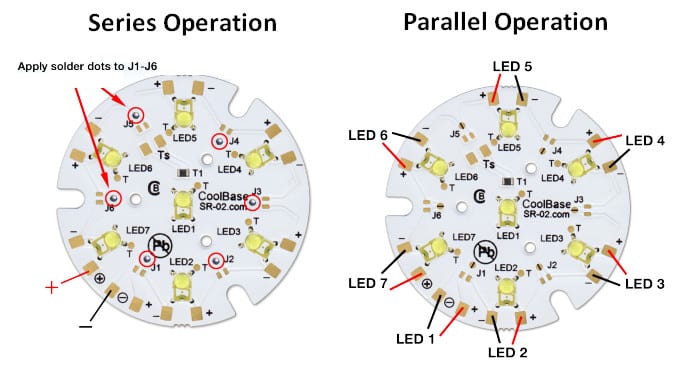
This LED module can be powered in parallel or series by adding 0-ohm resistors or solder dots.
Want to power this module from a voltage as low as 10VDC? Then check out the FlexBlock LED drivers. A single driver can power all 7 of these LEDs connected in series with any input voltage from 10V to 18V. Note that the maximum input voltage to the driver must be less than the total forward voltage of all series-connected LEDs.
Mixed Color LEDs
Need different color LEDs mounted to a single 7-Up module? A color-mixing version is available.
Stock
We usually keep a small number of this part in stock. However, we can produce virtually any quantity you require on demand. Please get in touch with us for lead times for orders above 1,000 pieces.
LED Binning
Order quantities of less than 140 pieces are produced from unbinned stock (cut strips). We can supply binned LED modules (built from full reels)) If you order in 140+ quantities, please contact us for binning details.
You can learn more about LED binning here.
| LED Color | ANSI White |
| Recommended Operating Current | 350 mA |
| Maximum Rated Drive Current | 1000 mA |
| Maximum Pulse Current | 1000 mA |
| Typical Forward Voltage | 19.6 Vf |
| Maximum Forward Voltage | 21 Vf |
| Lumens @ 350 mA | 665 lm |
| Lumens @ 700 mA | 1162 lm |
| Typical Wavelength | 3000 K |
| Color Rendering Index | 80 CRI |
| Beam Angle | 121° |
| Typical Forward Voltage | 19.6 Vf |
| Thermal Resistance | 10.5 °C/W |
| Maximum Recommended Junction Temp | 150 °C |
| Operating Temperature Range | -40 to 135 °C |
| Dimensions (L x W x H) | 40 x 40 x 5.0 mm |
| Weight | 6.9 g |
| Refer to the product datasheets for complete specifications. | |
|---|---|
A current-regulating LED driver is required between the power supply and the LED module to ensure that the LED is not powered above its maximum current rating. You can learn more about powering high-power LED modules here.
All drivers listed here are 100% compatible with the SR-02-3000-303 LED module. The driver you select will depend on your specific requirements.
| Product Information | Stock | Price | hf:att:pa_output-current | hf:att:pa_connection | hf:att:pa_dimming |
|---|
High-power LEDs include a primary optic for protection and light optimization. However, a secondary optic is often essential for better focus and light distribution.
All the optics listed here are 100% compatible with the SR-02-3000-303 LED module.
Note: The optics listed here may not be ideal for ultraviolet or infrared LEDs. You will need to test the optic for your specific application.
| Product Information | Stock | Price | hf:att:pa_beam-type | hf:att:pa_mounting |
|---|
To maximize life and reliability, a heatsink or alternate method of cooling is required to ensure that the junction temperature of the LED is kept well below its maximum temperature rating.
Refer to our Thermal Management articles for assistance selecting an appropriate heatsink from the available options here.
| Product Information | Stock | Price | hf:att:pa_length-hs | hf:att:pa_width-hs | hf:att:pa_height-hs | hf:att:pa_cw-filter | hf:att:pa_fin-type |
|---|
| RoHS Status | RoHS 3 Compliant |
| REACH Status | REACH Uneffected |
| Conflict Minerals Report | CMRT Rev 6.22 |
| Proposition 65 Statement | Proposition 65 |
| PFAS Declaration | PFAS Declaration |
| ECCN | EAR99 |
| HTS | 8543.70.71.00 |
| Country of Origin | CA |
Thermal Management
A suitable finned heatsink or other cooling method must always be used with the SR-02-3000-303 LED module to ensure that the junction temperature of the LEDs is kept well below the maximum rating specified in the Lumileds datasheet. The size of the heatsink will depend on the ambient temperature and the current used to power the LEDs.
Bench testing that we have conducted with SR-02 CoolBase modules powered at 700mA in an open-air environment and an ambient temperature of 25°C has indicated that a heat sink with a thermal rating of 9 C°/W or lower should be adequate. However, you must perform your own testing and analysis to determine if the heatsink you select is suitable for your application.
We recommend that the module be mounted to an aluminum or copper finned heatsink exposed to open air for optimal cooling. The module can be mounted to the heat sink in one of two ways:
- 40mm round pressure-sensitive, thermally conductive tape (Recommended)
- Arctic Silver thermally conductive adhesive
Before fastening the module to the heat sink, ensure that the two mating surfaces are perfectly flat and clean to maximize heat transfer to the heatsink. Mechanical fasteners are not recommended for this module.
A Vishay NTC 10K Thermistor (NTHS0805N02N1002J Thermistor datasheet) is mounted to the board to monitor temperature and can be used for foldback temperature control. For more information about using the thermistor, please review our SR-02 Onboard thermistor temperature measurement information in the SR-02 module datasheet.
The bottom of the LED module is electrically neutral, so it is unnecessary to electrically isolate the base from the cooling surface.
Connection
This LED module can be powered in parallel or series by adding 0-ohm resistors or solder dots.
Want to power this module from a voltage as low as 10VDC? Then check out the FlexBlock LED drivers. A single driver can power all 7 of these LEDs connected in series with any input voltage from 10V to 18V. Note that the maximum input voltage to the driver must be less than the total forward voltage of all series-connected LEDs.
Mixed Color LEDs
Need different color LEDs mounted to a single 7-Up module? A color-mixing version is available.
Stock
We usually keep a small number of this part in stock. However, we can produce virtually any quantity you require on demand. Please get in touch with us for lead times for orders above 1,000 pieces.
LED Binning
Order quantities of less than 140 pieces are produced from unbinned stock (cut strips). We can supply binned LED modules (built from full reels)) If you order in 140+ quantities, please contact us for binning details.
You can learn more about LED binning here.
| LED Color | ANSI White |
| Recommended Operating Current | 350 mA |
| Maximum Rated Drive Current | 1000 mA |
| Maximum Pulse Current | 1000 mA |
| Typical Forward Voltage | 19.6 Vf |
| Maximum Forward Voltage | 21 Vf |
| Lumens @ 350 mA | 665 lm |
| Lumens @ 700 mA | 1162 lm |
| Typical Wavelength | 3000 K |
| Color Rendering Index | 80 CRI |
| Beam Angle | 121° |
| Typical Forward Voltage | 19.6 Vf |
| Thermal Resistance | 10.5 °C/W |
| Maximum Recommended Junction Temp | 150 °C |
| Operating Temperature Range | -40 to 135 °C |
| Dimensions (L x W x H) | 40 x 40 x 5.0 mm |
| Weight | 6.9 g |
| Refer to the product datasheets for complete specifications. | |
|---|---|
A current-regulating LED driver is required between the power supply and the LED module to ensure that the LED is not powered above its maximum current rating. You can learn more about powering high-power LED modules here.
All drivers listed here are 100% compatible with the SR-02-3000-303 LED module. The driver you select will depend on your specific requirements.
| Product Information | Stock | Price | hf:att:pa_output-current | hf:att:pa_connection | hf:att:pa_dimming |
|---|
High-power LEDs include a primary optic for protection and light optimization. However, a secondary optic is often essential for better focus and light distribution.
All the optics listed here are 100% compatible with the SR-02-3000-303 LED module.
| Product Information | Stock | Price | hf:att:pa_beam-type | hf:att:pa_mounting |
|---|
To maximize life and reliability, a heatsink or alternate method of cooling is required to ensure that the junction temperature of the LED is kept well below its maximum temperature rating.
Refer to our Thermal Management articles for assistance selecting an appropriate heatsink from the available options here.
| Product Information | Stock | Price | hf:att:pa_length-hs | hf:att:pa_width-hs | hf:att:pa_height-hs | hf:att:pa_cw-filter | hf:att:pa_fin-type |
|---|
| RoHS Status | RoHS 3 Compliant |
| REACH Status | REACH Uneffected |
| Conflict Minerals Report | CMRT Rev 6.22 |
| Proposition 65 Statement | Proposition 65 |
| PFAS Declaration | PFAS Declaration |
| ECCN | EAR99 |
| HTS | 8543.70.71.00 |
| Country of Origin | CA |